

How Does the Flow Pattern Change in a Reducing Cross Tee Under Different Operating Conditions?
Nov 02, 2026
Leave a message
Introduction to Reducing Cross Tee Hydrodynamics
In industrial piping systems spanning petrochemical refining, power generation, food processing, and municipal water management[cite: 1], managing complex fluid distribution requires specialized fitting geometries. Among these, the reducing cross tee plays a critical role in merging or splitting fluid streams across lines of unequal diameters. Featuring four orthogonal openings where at least two ports have reduced branch or run dimensions, this fitting allows engineers to transition fluid volumes smoothly between main headers and auxiliary equipment lines.
However, fluid behavior inside a reducing cross tee is highly dynamic. Unlike standard equal tees, the spatial reduction in cross-sectional area introduces localized pressure drops, velocity gradients, and turbulent recirculation zones. Understanding how internal flow patterns evolve under varying flow rates, fluid viscosities, system pressures, and installation alignments is vital for preventing accelerated localized erosion, head loss, and uneven branch discharge.

Impact of Flow Velocity and Reynolds Number on Flow Distribution
The velocity of the incoming process fluid is the primary driver of turbulence and momentum distribution within a reducing cross tee.
Laminar Flow Regime (Low Flow Velocities)
At low flow velocities-typically corresponding to Reynolds numbers ($Re < 2100$)-fluid moves in predictable, parallel streamlines. As fluid enters the primary inlet and encounters the reduced branch ports, the transition occurs with minimal boundary layer separation. Inertial forces are balanced by viscous forces, resulting in an even volumetric flow split across symmetrical branch outlets. Head loss under low-velocity laminar conditions remains proportional to fluid velocity, minimizing energy consumption.
Turbulent Flow Regime (High Flow Velocities)
When flow rates increase significantly ($Re > 4000$), inertial momentum dominates. As fluid streams enter the reduction zone, the abrupt change in pipe diameter causes the boundary layer to detach from the internal fitting wall. This detachment generates secondary flow structures, including localized vortices and recirculation eddies immediately downstream of the reduction step.
High velocity forces the core fluid jet toward the primary outlet, while creating asymmetric pressure distribution at the side branches. In process monitoring applications, this velocity-induced imbalance can alter sampling accuracy by up to 15-20% compared to theoretical predictions. Furthermore, high turbulence intensifies impingement on the internal crotch radius of the tee, increasing mechanical wear over extended operation.
Role of Fluid Viscosity in Boundary Layer Behavior
Fluid viscosity dictates how effectively a liquid resists shear deformation when passing through geometric contractions.
Low-Viscosity Fluids (e.g., Water, Solvents): Low-viscosity liquids respond immediately to cross-sectional area changes. High momentum coupled with low internal friction promotes rapid boundary layer separation at sharp internal corners, yielding pronounced turbulent eddies and higher localized pressure drops.
High-Viscosity Fluids (e.g., Heavy Polymers, Crude Oils): High-viscosity fluids exhibit strong viscous dissipation. The thick boundary layer cushions the fluid core as it transitions through the reduced port. While this suppresses high-frequency turbulence and eddies, it establishes steep radial velocity gradients. The central core travels significantly faster than the fluid adhering to the internal walls, altering the effective split ratio between main runs and secondary branches.
To maintain predictable split ratios across both high and low-viscosity media, utilizing a precision-cast stainless steel cross tee with smooth internal transitions and controlled wall tolerances ensures uniform fluid distribution without inducing excessive fluid shear.
Effect of System Pressure Fluctuations and Fluid Phase
Operating pressure directly influences fluid density, particularly in compressible gas and vapor delivery systems.
In high-pressure liquid lines, incompressible fluids maintain constant density despite pressure changes. However, rapid pressure drops across a reducing branch can trigger localized cavitation if static pressure falls below the liquid's vapor pressure. Vapor bubbles form in high-velocity low-pressure zones near the reduction radius and collapse violently downstream, leading to noise, vibration, and pitting damage.
In compressible gas lines (e.g., compressed air, natural gas), pressure fluctuations alter volumetric flow velocity dramatically. A sudden downstream pressure drop causes gas expansion as it enters the smaller branch port. As gas velocity accelerates toward sonic thresholds, asymmetric flow patterns become severe. The high-velocity gas jet concentrates along the centerline of the reduced outlet, choking peripheral flow and causing flow distribution imbalances across neighboring manifold lines.
Engineering Manufacturing Precision and Alignment Integrity
Internal flow stability is not solely determined by operating parameters; the manufacturing quality of the fitting itself plays a pivotal role.
Internal Surface Finish and Radius Contours
Rough internal casting surfaces or sharp, unmachined interior intersections disturb fluid streamlines, triggering premature turbulent transition even at moderate velocities. Precision casting and advanced CNC machining create smooth internal radii that guide fluid smoothly through the 90-degree directional transition. Maintaining internal surface roughness levels ($Ra \le 0.8\ \mu\text{m}$) minimizes surface drag and reduces pressure drop coefficients ($K$-factors).
Upstream Pipe Alignment
Misalignment between connecting pipe spools and the fitting inlet distorts the entry velocity profile. An axial offset of just a few millimeters creates an asymmetric velocity distribution before the fluid even enters the reduction chamber. This amplification of turbulence leads to localized wall erosion, vibration, and piping fatigue.
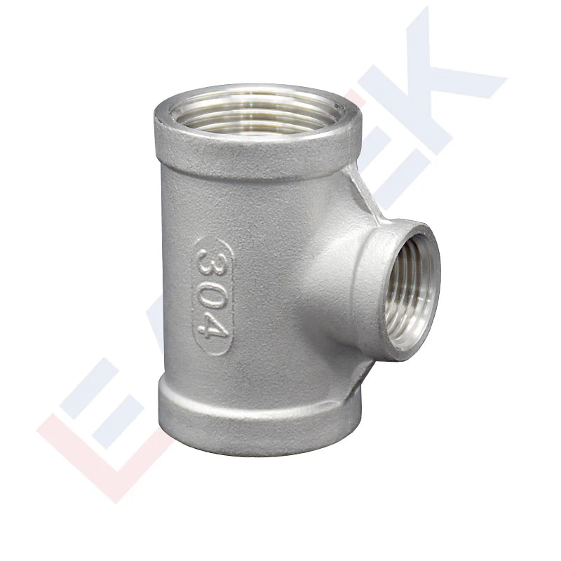
To ensure exact coaxial alignment during installation, engineers frequently pair reducing tees with precision-machined stainless steel 304l pipe fittings, guaranteeing gap-free joints and consistent internal diameters across all connection points.
Conclusion: Optimizing System Performance with Quality Fittings
Flow dynamics inside a reducing cross tee are shaped by the continuous interplay between flow velocity, fluid viscosity, system pressure, and mechanical design precision. Operating outside ideal conditions introduces turbulence, asymmetric split ratios, and elevated pressure losses that compromise overall system efficiency.
By specifying high-precision, corrosion-resistant fittings engineered with smooth internal geometries and strict dimensional tolerances, plant operators can stabilize flow patterns, protect downstream equipment, and extend system service life across demanding fluid control environments.